You have no items in your shopping cart.
 Email
Email Skype
Skype Chat
Chat
Tacho Pro 2008 July PLUS Universal Odometer Correction on Ford Focus Step by Step
Tuesday, August 16, 2016 10:19:27 AM Asia/Shanghai
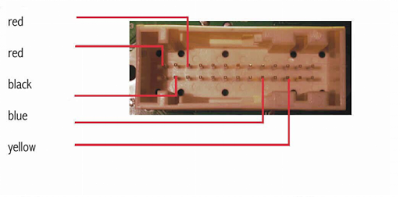
26pin white port
1.Pin 2 GND(-) black
2.Pin 9 RX (Data) blue
3.Pin 11 TX (Data) yellow
4.Pin 14 12V (+) red
5.Pin 16 12V (+) red
Processor version 1:
• Connect Pin 1 ( left side down) and pin 2 (right from pin 1), or connect black to test point 3 (TP3).
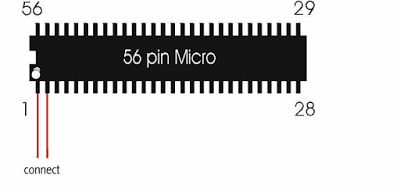
Processor version 2:
• Connect pin 1 (middle upside) and pin 2 (left beside pin 1), or connect black to testpoint 46 (TP46).
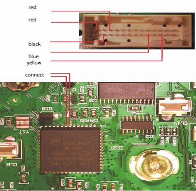
• Remove the cluster and open it.
• Connect the cables as shown in the picture.
• Select the menu Ford-Focus
• The Tacho Pro 2008 July PLUS Universal shows you the old value.
• Enter the new value.
• Verify the new value with OK.
Posted in News
By
sally sally
Post Comments